Planning of a MY24 Midsize Pickup
May
29
12:30 AM00:30

Planning of a MY24 Midsize Pickup

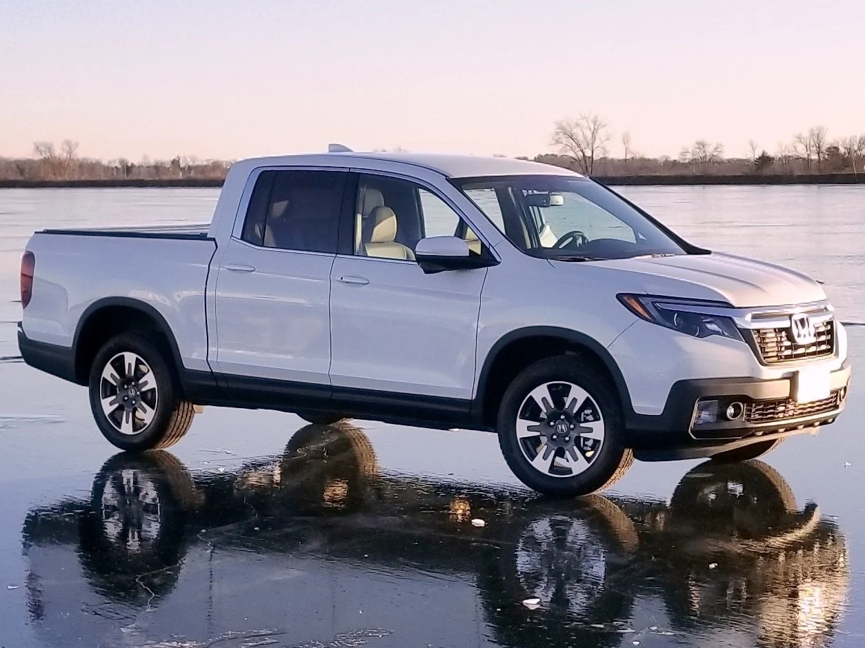
In this project a team of of five including myself planned out a MY24 Honda Ridgeline. Starting out we looked at the current mid-sized truck market. Aspects such as what vehicle are in this segment, who the customers are, and what the customer needs are. We then compared the various mid-size trucks, looking at multiple aspects and creating side by side comparisons. To better analyze these vehicle we created pugh diagrams comparing customers needs, vehicle attributes, and vehicle systems. We also looked at future regulatory requirements that would be needs for a MY24 vehicle.

Quality Function Deployment

Quality Function Deployment

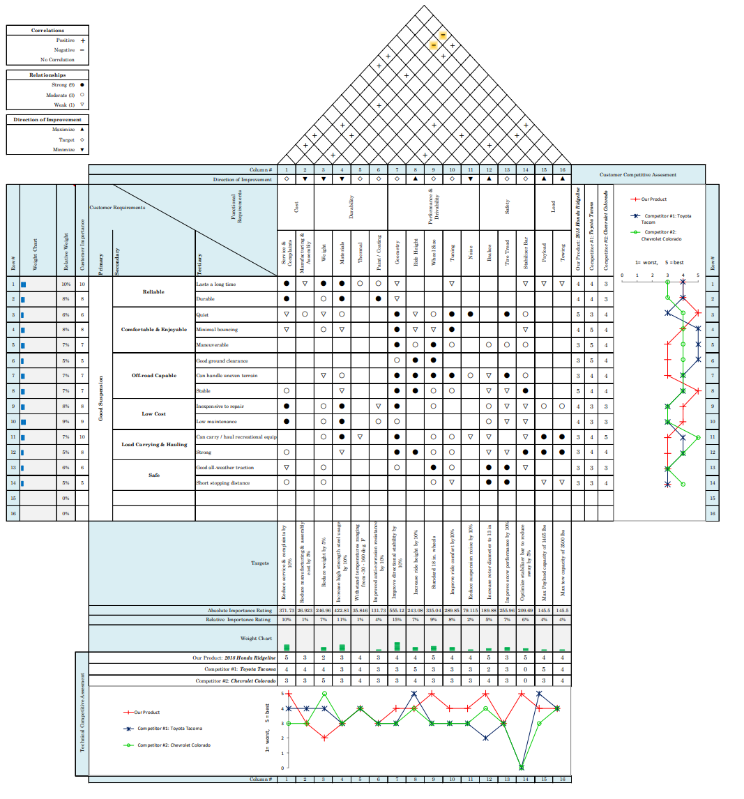
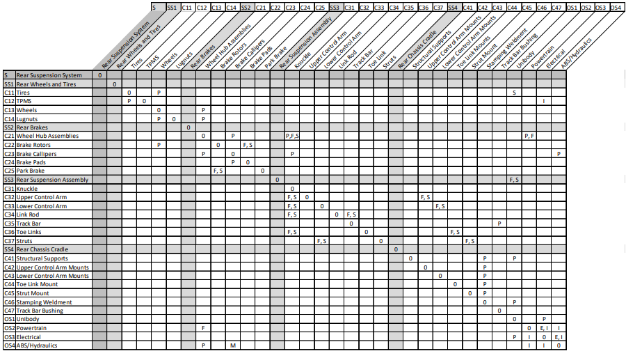
Next we cascaded requirements for our vehicle and looked at how our suspension system integrates together. To create our requirements and see their importance we created a quality function deployment (QFD) diagram to go from customer requirements to functional requirements. Next we looked at our selected vehicle system, the rear suspensions system. We were able to take our vehicle attributes and requirements and cascade them into systems and subsystem requirements. Finally we created and interface matrix and diagram to better organize how teams should communicate to make a cohesive system.

Interface Matrix

Interface Matrix

Finally we got into more specific planning with business plan, a conceptual design, and technology plan. Here with business plan we had to put in more detail projections details such as program timing, who would buy the vehicle, and how the vehicle is good financially. With the conceptual design and technology plan we outlined our dimensions and features for the MY24 Ridgeline. We also looked at technology challenges and risks with each new feature in our technology plan.

Reports:

View Event →
Self-Balancing Bicycle
May
27
1:30 AM01:30

Self-Balancing Bicycle

In this project, the concept of a self-balancing bike was investigated and tested on an actual bike. The dynamics of bicycles were investigated, and multiple possible models were found. Using the available information, preliminary PID values were created based on the model of an inverted pendulum. Code was then written for the pyboard that cleaned up the data from the sensor and controlled the actuation of the bicycle's handlebar based on the PID. However in testing it was found that the actuator was too slow to make the necessary corrections to stop the bicycle from falling over.

System overview with the green boxes being internal to the plyboard.

System overview with the green boxes being internal to the plyboard.

To improve this project the most needed improvement is with the actuator. With a faster linear actuator it is likely that the controller could successfully counter steer a few times to keep the bicycle upright. Upon using a faster actuator, other issue may be exposed such as in the cleanliness and accuracy of the data from the accelerometer. Furthermore since the bicycle balance is also dependent on bicycle speed and desired turn radius, further data may be needed to create a more robust system. Further divulging from the current system, a gyroscope could be used in place of the linear actuator. Such gyroscopic systems have been implemented on other two-wheeled vehicles successfully.

View Event →
Exploration of Vision Based Lane Detection and Departure Systems
May
25
2:30 AM02:30

Exploration of Vision Based Lane Detection and Departure Systems

In this project, multiple lane detection systems are explored. These systems range in sensor use, from lidar to visible light cameras. Different software approaches, including the Hough transform and machine learning are also explored for their advantages and disadvantages. Then in the second part of the paper, the Lane Departure Warning System is modified for use in a real-world test. The results of this test are then examined.

Report

View Event →
Taxi Dispatcher Program
May
24
3:00 AM03:00

Taxi Dispatcher Program

Created a taxi dispatcher program to find the optimal route to pick up and drop off a random selection of passengers. This program used various search methods to accomplish this. To implement the this my program created a goal state behind the nodes of the waiting customers. In searching for the customer, the search functions considered the fixed cost of adding and dropping off that passenger. Another search would be used to take the customer to his destination. After that the next customer would be sought out by searching for the goal state until no more customers are left. The taxi then ends there and doesn’t return to anything. So far as performance, I found that the breadth first and uniform cost searches have similar performance. Depth first search found a costlier path that had a greater chance of being significantly costlier as K and N got bigger. For small K and N, all methods were similar in the path cost, number of goal tests done, and states. The depth first search from casual observation seemed to be best at driving down the number of goal test done and actions taken but didn’t seem to be as useful for reducing the number of states.

Code

View Event →
Wireless Communicator
Feb
16
to Apr 16

Wireless Communicator

With this project I worked with four other students to build separate wireless communication boards. The end goal was a device based off of an ATMEGA256FR2 Xplained Pro that would communicate between the different boards using ZigBee.

The part of the schematic I was fully responsible for.

My responsibility in the project was to the design the circuitry to connect the board to a PC's serial port and to take everyone's schematics for their sections and combine them into one project. We however did our layouts and assembly separately.  This layout ended up being a little more trickier than that of my OBD-II Scanner. However I think this layout ended up better. I did notice after that I put some decoupling capacitors unnecessarily far away but I had the shortest distance to the antenna from the transceiver and the least number of vias.

My layout with the copper fill hidden.

My layout with the copper fill hidden.

For the assembly of the device I had the PCB tracing done externally but did everything else myself including soldering of parts in a reflow oven. During assembly it became apparent to me that one of the team members had made a mistake with the footprint for the debugger chip. Without that chip it became impossible to program the device trough USB. The device however could still be programmed through the serial port and powered by the USB. I didn't get around to programming however as a I ran out of time. The device should function as intended though once the short is found as the device is based on closely on the Xplained Pro.

Assembled communication board.

Assembled communication board.

This project allowed me to learn more about wireless communication, specifically ZigBee and the QPSK modulation scheme it uses. It especially opened my eyes even more to how important what I learned in linear systems analysis was to communication theory. Also since the continuity and coordination of the team I was working with wasn't as great as other teams I had been in. It gave me a great opportunity to learn about team coordination and management.

View Event →
LabVIEW UART
Nov
3
to Dec 1

LabVIEW UART

For this project I designed a LabVIEW program that can communicate using UART through a computer's serial port at a user defined baud rate. I started out by making a product brief  to set my goals and clarify what I was doing to my professor.  In the LabVIEW VI I put some preset commands that would send a preset command and parse the data sent back. These were commands specific to an STN1110 or ELM327 chip used to interpret between UART and various OBD-II signal protocols. However the raw output would still be displayed. Custom commands could also be sent to but the output would be as it is and not parsed. The program would run continuously and would stop when told to stop. This project allowed me to learn about designing LabVIEW VIs for testing that not only worked but were neat and commented.

View Event →
OBD Scanner
Oct
6
to Apr 17

OBD Scanner

  • Google Calendar ICS

I worked on a device with a mechanical engineer during undergrad that communicates with a 1999 Subaru Forester through the OBD-II port. The design goals I made at the beginning called for a device that could display different bits of information about the car and be easy to operate.

Fully assembled device.

Fully assembled device.

To do this my partner on I decided to set a reasonable size of 60 mm x 60 mm for the main PCB based on the size of components, available manufacturing abilities, and space constraints. My design called for the use of an STN1110 interpreter to translate between the ISO 9141-2 protocol of the Subaru and UART. For the microcontroller I decided to go with the TI MSP430G2553 as it is common and has a high voltage of 3.3 V. Since the STN1110 has a VDD voltage of 3.3 V I was able to simplify the design by only needing to put in a 3.3 V voltage regulator and not both 3.3 V and 5 V. Also on the PCB is a push button to cycle through commands, header pins for programming, and pins for output to a 16x2 LCD.

PCB layout

PCB layout

For the most part I tried to stick to using surface mount components, especially components in the 0603 package. But I had to use some through hole pin components and some non standard sized components which required the creation of custom footprints. Upon arrival the bare board and components I milled my own stencil, applied solder paste, and placed the PCB in a reflow oven. However afterwards an electrolytic capacitor was found to be off its pad and there was a also a missing connection with an IC, both of which were fixed with some hand soldering.

Assembled PCB laying in early case prototype.

Assembled PCB laying in early case prototype.

The device however didn't function as intended and I was required to troubleshooting. This included carefully looking over the datasheets to see how the components should be functioning and checking this against the actual device with an oscilloscope and multimeter. With the oscilloscope I checked to see if signals were actually being sent and if the STN1110 was functioning by checking the oscillator. I also checked the manufacturers forum for help and contacted them through their forum about my design. My design was confirmed to be a valid design for their chip to properly operate.

Checking oscillator with an oscilloscope.

Checking oscillator with an oscilloscope.

The device was able to display text on the LCD screen and send commands to the STN1110. However no response came back from the STN1110. The STN1110 was also supposed to send out a message over UART upon being awoken, but failed to do this. I decided to create a prototype on a breadboard using the same design. This design made it farther by having activity of the K and L lines used by the ISO 9141-2 standard and sending the data back over UART. The data returned didn't make sense however. I checked to see if it was the programming by adding a level converter and connecting the STN1110 to a PC through the serial port. This ended with similar results.

Checking for activity on data lines.

Checking for activity on data lines.

From this project I learned a lot. For one I learned about project management. In order to make sure my part was getting done at times that meshed with my partners we had to plan things out and make sure we were on the same page. I also learned that even the best laid plans can go bad and that when this happens it's an opportunity to learn more than you would have had things gone as planned. I also got more experience with schematic capture, PCB layout, and troubleshooting. I also was able to get exposed to related things such as the different OBD modes of operation, other protocols like CAN, and how ECUs are used in a vehicle.

View Event →