I worked on a device with a mechanical engineer during undergrad that communicates with a 1999 Subaru Forester through the OBD-II port. The design goals I made at the beginning called for a device that could display different bits of information about the car and be easy to operate.
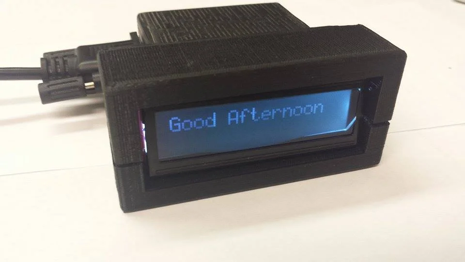
Fully assembled device.
To do this my partner on I decided to set a reasonable size of 60 mm x 60 mm for the main PCB based on the size of components, available manufacturing abilities, and space constraints. My design called for the use of an STN1110 interpreter to translate between the ISO 9141-2 protocol of the Subaru and UART. For the microcontroller I decided to go with the TI MSP430G2553 as it is common and has a high voltage of 3.3 V. Since the STN1110 has a VDD voltage of 3.3 V I was able to simplify the design by only needing to put in a 3.3 V voltage regulator and not both 3.3 V and 5 V. Also on the PCB is a push button to cycle through commands, header pins for programming, and pins for output to a 16x2 LCD.

PCB layout
For the most part I tried to stick to using surface mount components, especially components in the 0603 package. But I had to use some through hole pin components and some non standard sized components which required the creation of custom footprints. Upon arrival the bare board and components I milled my own stencil, applied solder paste, and placed the PCB in a reflow oven. However afterwards an electrolytic capacitor was found to be off its pad and there was a also a missing connection with an IC, both of which were fixed with some hand soldering.
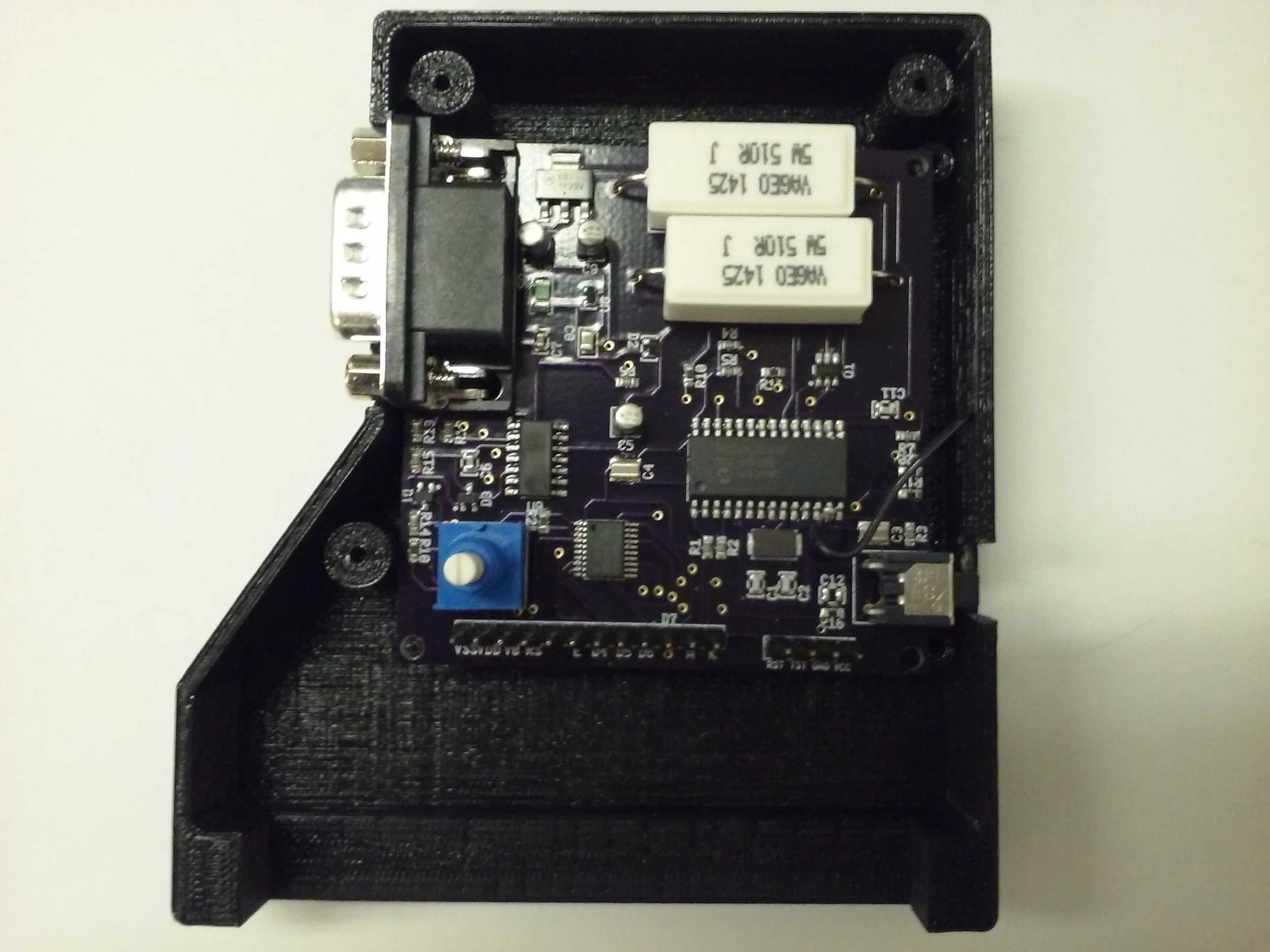
Assembled PCB laying in early case prototype.
The device however didn't function as intended and I was required to troubleshooting. This included carefully looking over the datasheets to see how the components should be functioning and checking this against the actual device with an oscilloscope and multimeter. With the oscilloscope I checked to see if signals were actually being sent and if the STN1110 was functioning by checking the oscillator. I also checked the manufacturers forum for help and contacted them through their forum about my design. My design was confirmed to be a valid design for their chip to properly operate.

Checking oscillator with an oscilloscope.
The device was able to display text on the LCD screen and send commands to the STN1110. However no response came back from the STN1110. The STN1110 was also supposed to send out a message over UART upon being awoken, but failed to do this. I decided to create a prototype on a breadboard using the same design. This design made it farther by having activity of the K and L lines used by the ISO 9141-2 standard and sending the data back over UART. The data returned didn't make sense however. I checked to see if it was the programming by adding a level converter and connecting the STN1110 to a PC through the serial port. This ended with similar results.

Checking for activity on data lines.
From this project I learned a lot. For one I learned about project management. In order to make sure my part was getting done at times that meshed with my partners we had to plan things out and make sure we were on the same page. I also learned that even the best laid plans can go bad and that when this happens it's an opportunity to learn more than you would have had things gone as planned. I also got more experience with schematic capture, PCB layout, and troubleshooting. I also was able to get exposed to related things such as the different OBD modes of operation, other protocols like CAN, and how ECUs are used in a vehicle.